
Have you ever looked at a bathroom renovation project and felt completely overwhelmed by where the pipes are supposed to go? You are definitely not alone. It’s a feeling that strikes fear into the hearts of many enthusiastic homeowners. You have the tile picked out, the new vanity is ready to go, but the stuff inside the walls remains a mystery.
This is where many people hit a wall—figuratively and literally. Plumbing jargon can feel like a foreign language. But here is the secret that professional plumbers don’t always tell you: you don’t need to be a math genius or an artist to understand your home’s plumbing. You need a roadmap. That roadmap is called a home plumbing riser diagram.
Without this diagram, you are essentially driving blind. Did you know that nearly 80% of DIY plumbing projects fail or run into major unexpected costs simply because there wasn’t a clear plan in place? That is a staggering number. But it doesn’t have to be your reality.
What Is a Home Plumbing Riser Diagram and Why You Need One
Before we grab our pencils, let’s make sure we are on the same page about what this drawing actually is.
Definition and Key Components
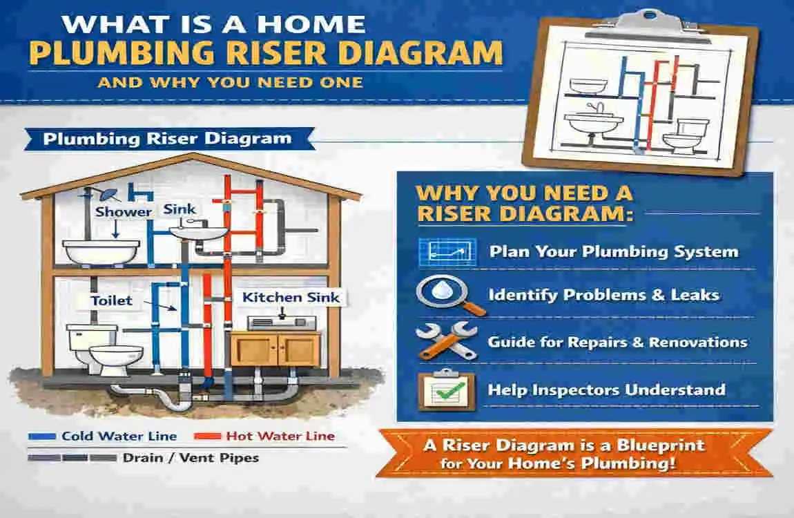
Imagine you could take an X-ray of your house, but instead of seeing wood studs and insulation, you only saw the pipes. Now, imagine flattening that 3D image onto a 2D piece of paper. That is what a plumbing riser diagram is.
Unlike a floor plan, which looks down on a room from above (like a bird’s-eye view), a riser diagram views the plumbing from the side (an elevation view). It focuses strictly on the vertical arrangement of your plumbing system. It shows how water rises from the ground to your top floor, and how waste flows from your toilet to the sewer.
Here are the core elements you will always see in these diagrams:
- Supply Lines: These are the pipes that bring fresh water in (usually pressurised).
- Drain and Waste Lines: The pipes taking the dirty stuff away (gravity-fed).
- Vents: The pipes that go up through the roof to let air in, so the water flows smoothly.
- Fixtures: Your sinks, toilets, showers, and tubs.
- Shutoff Valves: The emergency brakes of your plumbing system.
Benefits for DIY Beginners
You might be asking, “Is this really necessary for a simple bathroom upgrade?” The answer is a resounding yes.
First, it is the number one way to prevent leaks and code violations. When you draw it out, you catch mistakes on paper before you glue plastic pipes together. It is much cheaper to use an eraser than a hacksaw.
Second, if you are planning to sell your home or get a permit for a renovation, local inspectors often require this diagram. It proves you know what you are doing.
Third, let’s talk about your wallet. By creating this diagram yourself, you can save anywhere from 20% to 50% on professional fees. Even if you hire a plumber to do the actual installation, handing them a ready-made diagram significantly reduces their planning time.
Riser Diagram vs. Isometric or plan Views
This is where beginners get confused. You might have seen blueprints that look like a maze. Those are usually floor plans.
A floor plan shows you where the toilet sits in the room relative to the door. A riser diagram shows you how the pipe from that toilet connects to the main stack in the wall.
Here is a quick comparison to help you understand the difference:
FeatureFloor plan / BlueprintRiser Diagram
Perspective Top-down view (Bird’s eye) Side view (Elevation/Vertical)
Focus Room layout and spacing Pipe connections and vertical flow
Detail Level Shows walls, doors, furniture Shows pipe sizes, vents, traps
Best For Interior design & placement Plumbing installation & inspection
Beginner Ease Moderate High (once you understand the symbols)
To start, the riser diagram is superior because it simplifies the complex “web” of pipes into straight lines.
Essential Tools and Materials for Drawing a Plumbing Riser Diagram
You don’t need a degree in architecture or expensive equipment to do this. In fact, you probably have most of what you need in your junk drawer right now. Whether you are in a flat in Lahore or a suburban home in the US, these tools are universal.
Here is what you need to target the keyword “tools to draw plumbing riser diagram.”
Free Digital Tools
If you prefer working on a computer, you are in luck. There are fantastic free options available.
- Lucidchart or Draw.io: These are web-based diagramming tools. They offer free tiers with plenty of shapes. You can easily drag and drop squares and lines.
- Benefits: It is clean, easy to edit, and you can share it via email instantly.
Software Options
If you want to get a bit more technical or are planning a massive whole-home renovation:
- SketchUp: This has a learning curve, but it’s great for visualizing space.
- Bluebeam Revu: This is an industry standard for PDFs, though it can be pricey. Stick to the free trials if you need it for one project.
Analog Basics
For most DIYers, nothing beats the classic approach. It is tactile and easiest to do while walking around the house.
- Graph Paper: This is non-negotiable. The grid helps you keep lines straight and proportional.
- Pencils and Erasers: You will make mistakes. Do not use a pen until the very end!
- Ruler or Straight Edge: To keep your pipes looking like pipes and not spaghetti.
- Colored Pens/Pencils: Use Blue for cold water, Red for hot water, and Green or Black for drains/vents. This visual distinction makes the diagram readable instantly.
Pro Tips for Your Kit
- Scale: You don’t need to be perfect, but try a rough scale like 1/4 inch equals 1 foot. It keeps things fitting on the page.
- Code Book: Have a copy or a tab open of your local plumbing code (e.g., the IPC or a local Pakistani building code). You need to know required pipe sizes.
Budget Breakdown Table
Tool SetEstimated CostBest For
The “Analog” Basic $5 – $10 Quick sketches, small repairs, absolute beginners.
The “Digital” Free : $0 . Clean presentations, sharing with contractors.
The “Pro” Software $50 – $100+ Whole-home builds, complex renovations, aspiring pros.
Preparing to Draw Your Home Plumbing Riser Diagram: Site Assessment
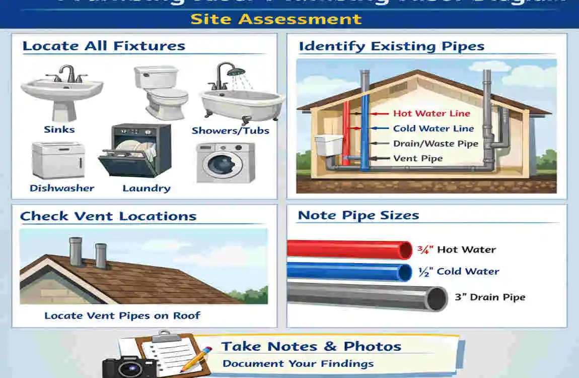
You cannot draw a map if you don’t know the terrain. Before you put pencil to paper, you need to do a little reconnaissance mission in your own home.
Gather Home Data
Grab a notebook and walk through your house. You need to understand the vertical levels.
- Measure Floor Heights: How high is the ceiling in the basement? How thick are the floor joists between levels?
- Inventory Fixtures: Go room by room. List every single item that uses water.
- Kitchen: Sink, dishwasher, fridge ice maker.
- Bathroom: Toilet, sink (lavatory), shower, tub.
- Laundry: Washing machine, utility sink.
- Note Locations: Is the upstairs bathroom directly above the downstairs kitchen? Knowing this helps you group pipes together to save materials.
Understand Local Plumbing Codes
This is the boring part, but it is the most important. Plumbing rules exist to keep sewer gas out of your house and keep fresh water clean.
- For our readers in Pakistan: Local municipal codes can vary, but many follow principles similar to the International Plumbing Code (IPC). Check for rules on venting.
- Common Rule: Every trap needs a vent.
- Pipe Sizes: A common pitfall is undersizing drains. For example, a toilet usually needs a minimum 3-inch drain, while a bathroom sink might only need 1.25 inches.
Sketch a Rough Floor plan First
Before doing the vertical riser, draw a quick top-down view. It doesn’t have to be pretty.
- Mark where the main water line enters the house.
- Mark where the main sewer line leaves the house.
- Draw lines connecting these to your fixtures.
- Tip: This rough floor plan acts as a cheat sheet when you switch to the vertical riser view.
Step-by-Step Guide: How to Draw a Home Plumbing Riser Diagram
Now, we get to the core of the project. We are going to build this diagram layer by layer. Follow these steps, and you will have a professional-looking result.
Set Up Your Drawing Scale and Layout
Take your graph paper (or open your software). Since a riser diagram is vertical, you might want to turn your paper to “portrait” Mode.
Draw your floor lines first. Draw a horizontal line at the bottom representing the basement floor (or ground level). Measure up using your scale (e.g., 4 squares = 1 foot) and draw the First Floor line. Go up again and draw the Second Floor line, and finally, the Roof line.
Label these lines clearly on the right side: “Basement,” “1st Floor,” “2nd Floor,” “Roof.”
Draw the Main Water Supply Line
We will start with the fresh water because it is usually easier.
Identify the Entry Point. Draw a vertical line rising from the ground (or the basement floor). This is your main water service pipe. Label it clearly (e.g., “3/4 inch Main Water Service”).
Add the Main Shutoff and Meter. Right where that line enters the house, draw a small symbol for a valve (usually looks like a bow tie) and a square for the meter. This is crucial for emergencies.
Split the System. Once inside, the water usually splits. Draw one line continuing as the Cold Water Main (use your blue pen). Then draw a branch to your Water Heater. From the Water Heater, draw a new line coming out—this is your Hot Water Main (use your red pen).
Add Fixture Branches and Risers
Now we need to get water to the sinks and toilets.
Mark Your Fixture Locations. Look at your floor lines. If you have a toilet on the first floor, draw a symbol for it sitting on the “1st Floor” line.
- Common Symbols: A circle for a sink, an oval for a toilet, a square for a shower. You don’t need to be an artist; keep it consistent.
Draw the Branches. From your main Blue (Cold) and Red (Hot) vertical lines, draw horizontal lines branching out to connect to your fixtures.
- Note: Toilets usually only get a Cold line (Blue).
- Note: Dishwashers usually only get a Hot line (Red).
Label Pipe Sizes. On these horizontal branches, write the size. Usually, branches to specific fixtures are 1/2 inch copper or PEX.
Incorporate Drain, Waste, and Vent (DWV) Lines
This is the tricky part where most beginners get confused. We are switching gears to the waste system. Grab your Black or Green pen.
The Main Stack. Draw a thick vertical line from the basement to the roof. This is your Soil Stack or Main Stack. It is the highway for waste going down and air going up.
- At the bottom, it curves and goes out to the sewer/septic.
- At the top, it pokes out the roof (this is the Vent Stack).
Connecting Drains. Draw lines sloping downward from your fixtures (sinks, toilets) to connect to this Main Stack.
- Important: In real life, these pipes must slope (gravity works!), but on a riser diagram, we often draw them as horizontal lines or slightly angled lines to keep the drawing clean.
- The Trap: Under every sink and shower, draw a little “U” shape or “P” shape on the line. This represents the P-trap that holds water and stops sewer smells. Note: Toilets have built-in traps, so you don’t draw one for them.
Connecting Vents. This is vital for flow. From the drain line of each fixture (after the trap), draw a line going UP. These vent lines need to connect back to the Main Stack above the fixture’s highest flood level.
- Think of it like a straw. If you put your finger over the top of a straw, water won’t flow out. The vent removes the “finger,” allowing wastewater to move.
Label Valves, Meters, and Shutoffs
You have the pipes, now add the control points.
Fixture Shutoffs. Every toilet and sink needs a shutoff valve underneath it. Draw small “bow tie” symbols on the supply lines right before they hit the fixture.
- Why? If your toilet leaks, turn off the water to the toilet, not the whole house.
Cleanouts. On your drain lines, specifically at the base of the stack in the basement, add a symbol for a “Cleanout.” This is usually a Y-shaped fitting with a cap. It allows a plumber to snake the drain if it gets clogged.
Review and Refine for Accuracy
Take a step back. Look at your drawing.
Trace the Paths.
- Put your finger on the main water inlet. Trace the blue line. Does it reach every toilet, sink, and shower?
- Trace the red line. Does it go to every shower and sink?
- Trace the drain from the top sink. Does it have a clear path to the sewer?
- Is every trap vented?
Add a Legend. In the corner of your paper, draw a small box.
- Blue Line = Cold Water
- Red Line = Hot Water
- Thick Black Line = Drain/Waste
- Dotted Line = Vent
- Circle = Sink
- Bowtie = Valve
This legend makes your diagram readable to anyone—including the city inspector or a future contractor.
Common Mistakes to Avoid When Drawing a Plumbing Riser Diagram
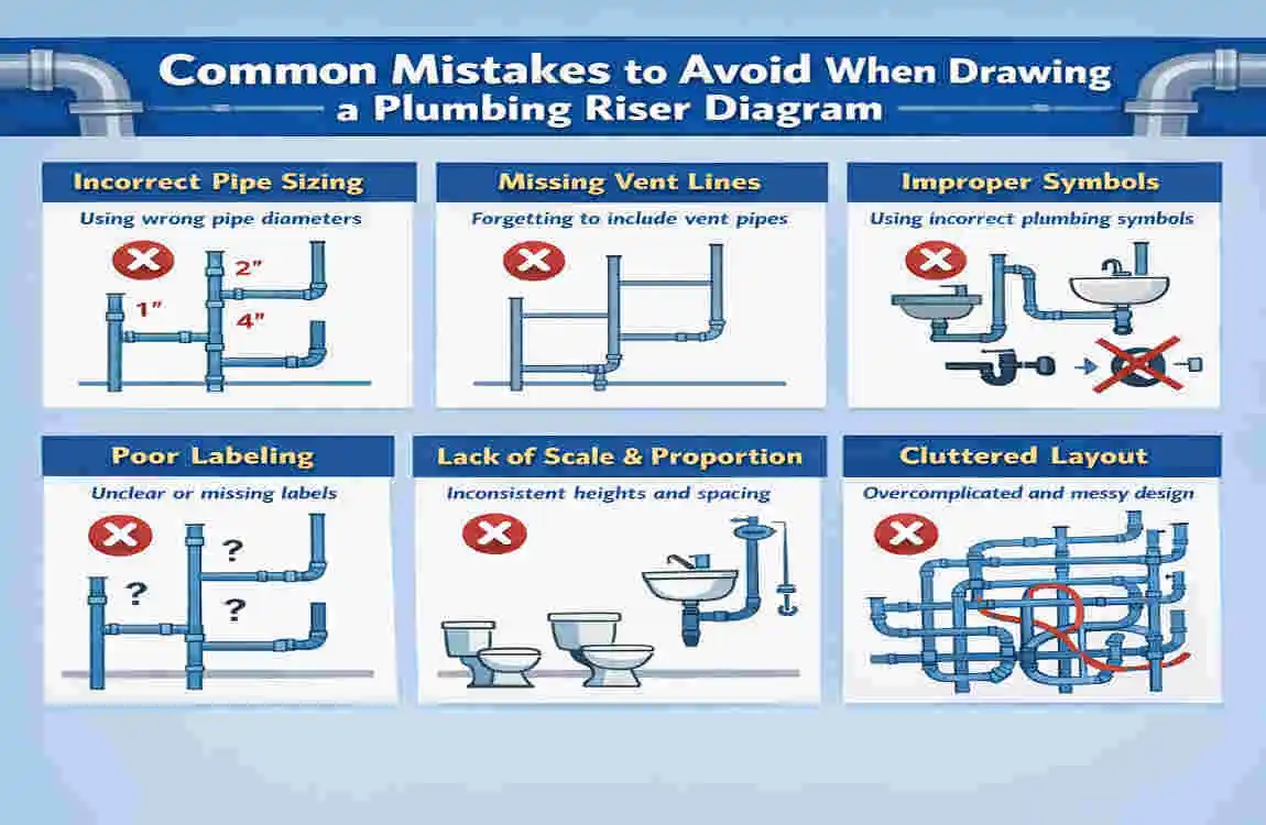
Even with a guide, it is easy to make errors. Here are the most common “oops” moments beginners make, so you can avoid them.
Forgetting the Vents
We cannot stress this enough. New DIYers often focus on the water and the drain, but forget the air.
- The Consequence: If you don’t include vents in your diagram (and your build), your drains will gurgle, drain slowly, or suck the water out of the traps, allowing sewer gas into your home.
- The Fix: Ensure every fixture drain has a vertical line to the roof or connects to a main vent stack.
Wrong Scaling or Layout
While you don’t need architectural precision, a wildly off-scale drawing can hurt you.
- The Mistake: Drawing a pipe run as 2 inches long on paper when it is actually 40 feet in real life, without noting it.
- The Consequence: You might think you can vent a fixture horizontally, but in reality, the distance is too long for code.
- The Fix: Always write the estimated length of the pipe run next to the line on your diagram (e.g., “10 ft run”).
Ignoring Pipe Expansion
Pipes expand when heated and contract when cooled.
- The Mistake: Drawing straight, rigid lines for long hot water runs without room for movement.
- The Fix: For very long runs (especially PEX or copper), note “Expansion Loop” or offsets to prevent pipes from rubbing against wood studs.
Quick Fixes Table
MistakeSymptom in DiagramHow to Correct
S-Traps Drain line goes down immediately after trap Change to P-Trap (horizontal run before dropping)
Wet Venting Draining a toilet through a sink drain Check local code; often illegal for DIYers
Undersized Pipe Labeling a toilet drain as 2″ Change to 3″ or 4″ (standard for soil lines)
Advanced Tips: Customizing Your DIY Plumbing Riser Diagram
Once you have the basics down, you can add some “pro” features to your diagram. These are great if you are building a modern, high-efficiency home.
Adding Expansions for Hot Water
If you have a large home, waiting for hot water on the second floor is annoying. You can add a Recirculation Line to your diagram. This is a loop that connects the far end of the hot water line back to the water heater. It requires a pump symbol and a check valve symbol. Including this in your plan shows high-level thinking.
Smart Home Integration
Are you installing a smart water monitor like a Moen Flo or Phyn? Add this to your riser diagram right after the main meter. It is an electrical component, but it lives on the plumbing riser. Mark it clearly so you know to leave space (and an electrical outlet) for it.
Digital Export for Pros
If you used software like Draw.io, save your file as a PDF. This allows you to email it to suppliers. You can say, “Here is my riser diagram, please give me a quote for all the PVC and copper fittings shown.” This makes you look incredibly professional and ensures you get accurate quotes.
When to Call a Professional Plumber
We are huge advocates for DIY, but there is a time to put the pencil down and pick up the phone. A riser diagram is a planning tool, but executing it is physical work.
Complex Multi-Story Homes If you have a three-story home in a dense area (like an older neighborhood in Lahore or New York), the venting requirements become very complex. “Wet venting” multiple floors is tricky math. If you are unsure, hire a pro to review your diagram. You draw it, they check it.
Major Main Line Work If your diagram involves moving the main sewer stack or tapping into the city water main, you usually need a licensed professional by law.
The “Gut Check” If you look at your finished diagram and it looks like a bowl of spaghetti that you don’t understand, don’t start cutting pipes. Call a service for an inspection or consultation. It is cheaper to pay for an hour of advice than to pay for a week of repairs.
Frequently Asked Questions (FAQs) About How to Draw a Home Plumbing Riser Diagram
Q: What is the best free software for beginners to draw a home plumbing riser diagram? A: Lucidchart and Draw.io are the best free options. They are web-based, user-friendly, and offer pre-made shapes that work perfectly for pipes and valves, without CAD skills.
Q: How long does it take to create a plumbing riser diagram? A: For a standard bathroom remodel, you can sketch a functional diagram in about 30 to 60 minutes. For a whole-house system, plan to spend 2 to 4 hours measuring and drawing.
Q: Is a riser diagram required for home sales or renovations? A: It depends on your location. In many places, including parts of Pakistan and the US, a riser diagram is required to get a building permit for major plumbing changes. It is not usually required for a simple sale, but it adds immense value to the buyer.
Q: Can I draw a plumbing riser diagram by hand? A: Absolutely. In fact, most inspectors accept neat, hand-drawn diagrams on graph paper. You do not need a computer generated printout as long as it is legible and labeled correctly.
Q: What is the difference between a riser diagram and an isometric drawing? A: A riser diagram is a 2D elevation (flat side view). An isometric drawing is a 3D representation drawn at a 30-degree angle. Isometric is more detailed for showing exactly how pipes turn in walls, but Riser is simpler and sufficient for most basic permits.
Q: How do I know what size pipes to label on my diagram? A: You must consult your local plumbing code (like the IPC). generally, toilets need 3″ drains, sinks need 1.5″ drains, and main water supplies are 3/4″ or 1″.